HVAC Chiller Arrangement- Series
- Scholenberg
- Dec 12, 2021
- 7 min read

Series chillers are another method of operating more than one chiller in a plant. This design concept resolves the mixed flow issues found in parallel chiller designs. The chillers can be preferentially loaded as well, allowing the designer to optimize chiller performance. Series chiller systems are straightforward to design and operate.
1.0 Basic Operation

Figure 39 shows two chillers in the series. All the system flow goes through both chillers. As a result, the water pressure drops through the evaporators are additive. The chilled water loop can be either a constant or variable flow. Variable flow systems increase the complexity but offer significant pump savings. A condenser loop is required for water-cooled chillers. This includes a condenser pump, piping, and a cooling tower or closed circuit cooler. The condenser loop operates whenever the chillers operate.
If both chillers are the same and the condensers are piped in parallel, the lead chiller will accomplish about 45% of the system load and the lag chiller will accomplish about 55% of the system load. This occurs because the lead (downstream) chiller is supplying chiller water at the system setpoint (typically 44°F). The lag (upstream) chiller is supplying chilled water at approximately 48.5°F to the lead chiller. The reduced lift for the lag chiller allows it to provide more cooling capacity.
For constant flow systems, the chilled water temperature range varies directly with the load. Depending on the load diversity, the chiller design temperature range will be less than the range seen at each load. In this case, the chiller range is 8°F while the cooling coil range is 10°F (Refer to Piping Diversity, page 25). The overall result is an increased chilled water pump and pipe capital cost plus higher annual pumping cost.
A problem with series chillers is the high flow rate and the low-temperature range through the chillers. The high flow rate can result in high water pressure drops. Since the chillers are in series, the pressure drops of the chillers must be added. If the typical 10°F system temperature difference is maintained, then single pass evaporators should be considered. This will lower the pressure drop to an acceptable level.
2.0 Basic Components
2.1 Chillers
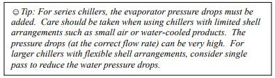
Chillers selected for series applications require special consideration. Special care should be taken when using smaller chillers with limited shell arrangements such as small air or water-cooled chillers. The pressure drops are typically designed to be acceptable with the flow rates around 2.4 USgpm/ton. When the flow is increased to 4.8 USgpm/ton as in series applications, the pressure drop rises significantly. A 10 ft pressure drop at 2.4 USgpm/ton will be a 40ft pressure drop at 4.8
USgpm/ton. With larger chillers that offer flexible shell arrangements, single-pass shells can be used to lower the pressure drop.
Two single pass shells in series will be comparable to a typical two-pass shell in water pressure drop. The chillers will not see the same duty; the lead chiller has a different lift requirement than the lag chiller. The more difficult duty is the lead chiller. The selections must be done so that the chillers operating at the specific conditions will provide the required capacity. The actual chiller output and performance will most likely be different. Selecting both chillers to be the same machine and able to meet the requirements of the lead position allows the chillers to be interchangeable when the plant load is less than one chiller’s capacity. There is some performance loss when the chiller is operated in the lag position because the chiller is not optimized for that specific lift. It is possible to select two different chillers, each optimized for their operating conditions. This arrangement will be slightly (about 2%) more efficient but the chillers will not be interchangeable.

Increasing the chilled water temperature range affects series chillers differently than parallel chillers. As the range is increased, series chillers will generally outperform parallel chiller arrangements. This occurs because the cascading effect of series chillers enhances the chillers’ performance.
2.2 Pumps

Pumps can be constant or variable flow. Pump basics are covered in Pumping Basics. The chilled water pump is sized for the design flow rate. The chilled water design head will be impacted by having to add the chiller pressure drops together. Figure 40 shows a variable primary chilled water pumping configuration. These pumps provide redundancy along with the ability to vary the flow through the series of chillers. Each chiller also has its own cooling tower and pump. The pumps and piping are sized for the design condenser flow for each chiller. Whenever the chiller operates, the condenser pump operates.
2.3 Cooling Towers
Water-cooled chillers will require cooling towers. Figure 40 shows dedicated cooling towers for each chiller. A common cooling tower is also possible but not common for series chillers. Cooling towers are covered in Cooling Tower Basics.
3.0 Series Chillers Sequence of Operation
Series chillers can be preferentially loaded. As the chiller plant load increases, the lead (downstream) chiller will load from 0 to 100% capacity to meet it. Once the lead chiller is loaded (which is likely to be about 45% of plant capacity) the lag chiller is started. Here are three ways to operate the lag chiller:
1. Set the upstream chiller chilled water setpoint to bring on the chiller once the downstream chiller is fully loaded. For example, if the downstream chiller is fully loaded when it receives full water flow and an eight-degree temperature difference, the upstream chiller’s discharge temperature should be set to the plant design temperature plus the eight degrees (i.e. 44°+8° = 52°). This will preferentially load the downstream chiller. The downstream chiller will operate at full load while the upstream chiller will ramp up as the chiller plant load goes from about 45% to 100%. If the downstream chiller is offline for any reason, the upstream chiller will not be able to assume its role unless the chilled water setpoint is changed, either manually or remotely.
2. Move the upstream chiller sensor downstream of both chillers. This will preferentially load the upstream chiller. Once the upstream chiller cannot maintain the chilled water supply temperature, the downstream chiller will start and provide the balance of the load.
3. Modern chiller controllers can allow two or more chillers to communicate. In this arrangement. Either chiller can be the first chiller on, assuming they were both selected to do the lead chiller duty. Once the first chiller is fully loaded, the second chiller will start and the load will be evenly balanced between the two chillers. This can result in about a 2% improvement in annual chiller energy usage. Where possible, this method is recommended.
Staging on the pumps and cooling towers is similar to that outlined for single chillers. Refer to Single Chiller Sequence of Operation.

4.0 Constant Flow Series Counterflow Chillers
Series counterflow chillers are shown in Figure 41. This arrangement differs from the series chillers system shown in Figure 40 in that the condenser flow passes through both chillers in series, counterflow to the chilled water. Series counterflow condenser water improves the chiller performance as explained in the series counterflow chiller example.

Series counterflow chillers can be 5 to 7% more efficient than a single chiller at design conditions and save up to 20% of chiller energy annually. However, the condenser pump is sized for the entire system flow (in this case 2400 US GPM) and this pump must operate whenever any chiller operates. The result is increased pump work annually. Series chillers with parallel towers may outperform series counterflow chillers depending on the chiller savings versus pump losses. Where series counterflow chillers can be advantageous is in large primary secondary chiller plant systems.
5.0 Using VFD Chillers in Series Arrangements
A common practice in selecting chillers for series applications is to select both chillers to be the same and meet the most demanding lift. For centrifugal chillers, this means the compressors are selected for the largest lift on a design day. The chiller that is then used as the lag chiller provides too much lift and is not optimized. A solution to this is to use a centrifugal chiller with a VFD as the upstream chiller. This has two advantages:
1. During periods when the chiller plant load is less than 45% (about the limit for one chiller) the VFD chiller can be used and take advantage of any condenser relief available. Considering this is a part load situation, condenser relief should be significant.
2. When two chillers are required, the VFD chiller can use the VFD to optimize its performance while being used in the lower lift application.
Both chillers do not need to have VFDs. Either chiller will work in either application (lead or lag) without a VFD.


6.0 System Comparison
The previous section covered several common chiller system designs based on constant flow systems. Each system has strengths and weaknesses in terms of design. A key operating parameter is the annual energy usage.

Table 5 shows the design condition power usage of the chiller systems covered in the last section. As it can be seen, all the systems have the same full load performance. The series counterflow chillers provide better performance than the other systems because of the cascading effect. At nominal AHRI conditions, these chillers would perform the same as the other chillers.
Table 6 shows the annual energy usage of the various chiller systems. This tells quite a different story. The single and parallel chiller plants perform the same because the parallel system operates the two chillers at all load points. There is no easy way to shut down a chiller in a parallel, constant flow arrangement.

The series chillers outperformed the parallel chillers. The water pressure drops, however, were held constant. If the water pressure drops through the series chillers had been increased as is typically the case, then there would have been little or no difference.
At design conditions, the series counterflow chillers appeared to have a distinct advantage, however, the pumping penalty on the condenser side actually increased the overall annual energy usage. Here are some relationships that can be used:
Design performance is a poor indicator of annual performance. There is no way to tell which system will perform the best by reviewing the design condition performance.
The sequence of operation is a major factor. How the system operates will vastly affect the savings.
In constant flow systems, pumps are a major component. Although the pump motors are only 25% the size of the chiller, they use more than 60% of the power that the chiller uses.
Increasing the chilled water temperature range will improve the performance of the series chiller systems relative to other chiller systems. The chillers will operate more efficiently and the pressure drop penalty will be less of an issue.
Variable flow systems can save significant pump energy. They will be discussed in future sections.


Comments