HVAC-Heat Recovery in Chillers
- Scholenberg
- Dec 12, 2021
- 8 min read

Chiller plants collect all the energy released in the building. In addition, there is an additional 25% more energy from the chillers themselves because of the compressors. This represents a lot of heat that can be used for other processes within the building. The challenge is that this is low-grade, 95°F heat that is not very useful for anything. The solution is to use either heat recovery chillers to raise the temperature of the water to a temperature that is useful. Common uses for heat recovery water are:
HVAC system reheat
Domestic hot water
Snow melting
Process applications
1.0 Load Profiles
A key issue with heat recovery is to understand the load profile of the chiller plant and the load profile of the system that requires the heat. It is absolutely necessary to have a cooling load at the same time there is a requirement for heat. While this may seem obvious, many reheat systems are designed to use heat recovery hot water when the chiller plant is producing little or no heat.

In many cases, the cooling load is declining as the heat load is increasing. An example is reheated for VAV. Without a cooling load, no heat can be collected. An analysis must be performed to identify the size and time of the heating load. Figure 56 shows the annual cooling load and annual heating load for a building. The shared underneath both curves is the amount of heat available for recovery. The size of the heat recovery chiller should be the highest point in this shared area. For this example, the intersection of the cooling and heating profiles during September is the correct size. HVAC systems that require winter chilled water, such as fan coils, buildings with process loads, etc., tend to be good candidates for a heat recovery chiller because of the large amount of time when there is simultaneous heating and cooling.
2.0 Heat Recovery Chillers
There are two types of heat recovery chillers. Both can produce condenser water from 105 to 115°F rather than the normal 95°F. Figure 57 shows the piping arrangement for a single condenser heat recovery. Typically a heat exchanger is used to transfer the heat from the condenser loop into the hot water loop. This is done to avoid contamination from the open tower condenser loop entering the hot water loop. Using a heat exchanger introduces another approach to the system since the condenser water will have to be about 2°F warmer than the hot water loop.

The second type has an additional condenser shell that allows the rejected heat to be rejected to a separate heat recovery water loop. Since the hot water loop is heated directly by the refrigerant, warmer water is possible for the same condensing pressure (compressor work) than with single condenser recovery.
When heat recovery is not required, the condensing pressure can be lowered and the heat rejected to the cooling tower at the typical condenser water temperature range. This reduces the compressor work and improves the chiller efficiency. It is recommended that the chiller has a dedicated cooling tower rather than a common cooling tower with other chillers in the plant. This will avoid raising the condenser water to the other chillers and lowering their performance unnecessarily.
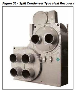
Figure 58 shows a split type heat recovery chiller. The hot water loop flows directly through the chiller. Any additional heat not used by the hot water loop is collected in the condenser loop and rejected by the cooling tower.
Split condenser chillers are more expensive but avoid the heat exchanger and other piping requirements.
Heat recovery puts additional demand on either type of heat recovery chiller. To raise the refrigerant condensing temperature high enough to produce hotter water, the compressor must work harder. This lowers the chiller efficiency and must be taken into account when evaluating the use of heat recovery. Even when the chiller is operating in “normal” mode, the chiller efficiency will be less than a standard chiller because it is not optimized for the lower lift application.
Another major issue is part-load performance. As a centrifugal chiller unloads, it becomes more and more difficult for it to produce high lifts. If the lift of the chiller is exceeded, it will stall and then surge, which can severely damage the compressor. Most heat recovery load profiles increase the heating requirement as the cooling load reduces, setting up a situation where the chiller will be partially loaded but expected to produce hot water.
To remedy the problem, hot gas bypass should be included with any heat recovery chiller. While this will protect the chiller from surging, it may also waste a lot of power. For instance, if the hot gas valve opens at 25% capacity, any output between 0 and 25% capacity will consume the power used at 25% capacity. In short, the chiller may become a very large electric resistance heater!
2.1 Heat Recovery Chiller Control
When a chiller is in heat recovery mode, it attempts to produce hot water as well as chilled water. There are two common methods of control. The first is for the chiller to maintain a common condenser return water temperature. For example, consider a chiller that is intended to produce 105°F supply hot water with 95°F return hot water at full load. This control sequence will attempt to maintain the return water temperature at 95°F. The supply hot water temperature will then fluctuate between 95 and 105 °F depending on the amount of heat rejected.
Basing the control on the return water temperature is easier on the chiller in terms of light load lift. During the period of light cooling load, the required condensing pressure drops as shown in Figure 59. This reduces the chance of a surge or stall situation and reduces the use of hot gas bypass. A fixed return hot water system (during heat recovery mode) will mean the supply hot water temperature fluctuates as the heating load changes (assuming a constant hot water flow rate. The changes are generally small somewhere between 3-5°F. The boiler can supplement the heat recovery and add enough heat to maintain the return water temperature. The boiler control should be set up to provide 95°F return water during heat recovery. If desired, during non-heat recovery heating mode, the boiler can operate on a fixed (e.g. 180°F) supply water temperature.
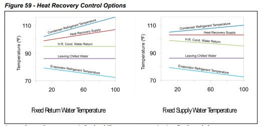
A second control arrangement is for the chiller to attempt to maintain a fixed supply hot water temperature. This arrangement provides a constant supply temperature (105°F for example) for the hot water system. It also requires the chiller to produce design condition refrigerant condensing pressures even at very low chiller loads. This arrangement is harder on the chiller and will generally produce less heat recovery than a control system that maintains a constant entering water temperature.
Raising the hot water temperature is accomplished through the cooling tower and bypass valve control. To raise the water temperature for either single shell or split shell heat recovery, either the cooling tower or the chiller bypass valve must be modulated to meet the required hot water temperature. The cooling tower water temperature will be the same as the hot water temperature! Normal cooling tower operation will need to be overridden. When there is no heat recovery required, (no heating load) the control system should lower the condenser water temperature and follow whatever control sequence is being used for conventional chillers (See Cooling Tower Controls).
2.2 Heat Recovery Chiller Selection
Proper heat recovery chiller selection requires a clear understanding of the chilled water and hot water load profiles. To produce the best results, the chilled water plant design should be optimized to take full advantage of the load profiles. A common practice is to design the chilled water plant as if there was no heat recovery and then pick one of the chillers and rate it as a heat recovery chiller at design cooling load conditions. The total heat of rejection from a heat recovery chiller operating at design cooling is 1.25 times the design cooling capacity. While this sounds like a significant amount of energy recovery, it does not mean the system will actually produce it. The chiller will only produce this amount of heat recovery if it is fully loaded and all the other design parameters are met. The following issues should be considered when selecting a heat recovery chiller:
Chiller Sizing. The chiller should be sized as close to the expected cooling load during heat recovery as possible. It is important to have the chiller operating as close as possible to 100% cooling load during heat recovery to provide the best refrigerant lift and to use the least amount of hot gas bypass. The optimal size requires annual energy analysis.
Hot Water Temperature Ranges. Chillers are typically selected based on a 10°F range while hot water systems are often designed for a 20°F range. Using a 20°F range for the chiller is not recommended. Using tertiary piping for the chiller on the hot water loop allows the chiller to be in a different temperature range and the pressure drop of the chiller is avoided when not in use.
Hot Water Supply Temperature. Heat recovery chillers are limited in what they can produce. The higher the water temperature, the more useful it is for heating. However, high supply water temperatures are harder on the compressor, reduce the stable compressor envelope and lower the chiller performance.
Boiler Interaction. It is easy to become fixated on maintaining the hot water supply setpoint when the real goal is to produce as much heat recovery as possible. Understand how the boiler and chiller interact to produce hot water. Try to collect as much heat as possible from the chiller (even if the supply water temperature is not met) and trim with the boiler to meet the required heating load.
Compressor Lift Limitations. The higher the compressor lift requirement, the smaller the stable compressor envelope, and the sooner the compressor lift will be exceeded at part load. Understand at what percentage of cooling load the compressor will no longer maintain the required lift. Operation below this point will require hot gas bypass. Select the hot water control sequence that produces the best result. Basing the hot water control on the return water temperature may produce more heat recovery without hot gas bypass.
2.3 Chilled Water Plant Design for Heat Recovery
Any chiller plant design can include a heat recovery chiller. Generally, only one chiller in multiple chiller plants is a heat recovery type. It should be the first chiller that is activated during cooling. Another design possibility is to add a heat recovery chiller in the chilled water return line but in a tertiary loop. This chiller will reduce the load on the main chillers by lowering the return water temperature. It will also allow all the heat recovered in the building to be available for heat recovery.
The chiller plant design can be “tuned” to optimize heat recovery. Here is a list of things to consider:
Pick a chiller size that matches the chilled water load during heat recovery.
Backload the chiller by the placement of the decoupler (Refer to Primary Secondary Systems).
Consider series chillers where the upstream chiller is the heat recovery chiller.
Use chilled water reset so the lift is reduced during the heat recovery operation.
Evaluate a VFD chiller, which will operate more efficiently when not in heat recovery mode.
Avoid low chilled water design temperatures.
2.4 Impact on the Rest of the HVAC Design
Where heat recovery will be used for heating, the chiller should tie into the boiler return. A tertiary loop is recommended so the chiller heat recovery temperature range can be different from the boiler loop range. The flow rates for the boiler and the heat recovery will most likely be different as well. A tertiary loop also allows the pressure drop through the heat recovery chiller to be avoided when heat recovery is not possible.
Most heating systems are designed for 170°F average water temperature. The use of heat recovery will require the heating system to operate with water in the 105 to 115°F range. Whereas single row heating coils in terminal heating units would have worked with a conventional design, now 3- or 4- row heating coils may be required. These coils will add to the capital cost of the project. Further, they will increase the fan static pressure drop every hour the fan system operates.
Domestic hot water systems range from 120°F for showers, baths, etc to 140°F for kitchens. These temperatures exceed the capabilities of a heat recovery chiller, however, a heat recovery chiller can be used for preheating. When heat recovery is used for domestic hot water, local codes may require an isolating heat exchanger.


Comments