Low Delta T Syndrome in HVAC
- Scholenberg
- Dec 12, 2021
- 10 min read

Low delta T syndrome occurs when the design chilled water temperature range is not maintained. Any variable flow system can experience low delta T and the problem is exacerbated at part load. In severe cases, the chilled water range has dropped from 12°F design to 2°F. When this occurs, the flow rate must be increased significantly to provide cooling in the building. The following section will expand more on causes and solutions for low delta T syndrome.
1.0 Low Delta T Example
Figure 63 shows a basic primary secondary loop operating at full load. In this example, the system design load is 400 tons, the flow rates and temperatures are at standard AHRI conditions and the load has a two-way control valve. The loop with the chiller is called the primary loop. The loop with the load is the secondary loop. The common pipe is sometimes referred to as the decoupler.
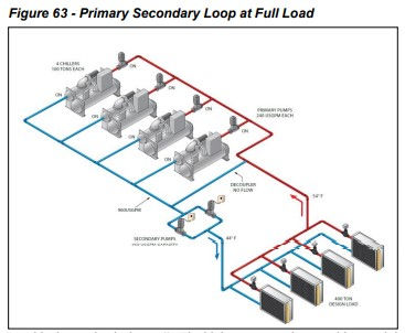
At full load, the design flow of 960 USgpm passes through the chillers, the two pumps, the load, and back to the chillers. There is no flow through the common pipe. At first, it would appear that the flow is being pumped twice. Although this is true, the total head is split between the two sets of pumps. The primary pumps are only sized for the primary loop of the system. This means that they are sized for the chiller pressure drop and any fittings in the primary loop. The secondary pumps are sized for the pressure drop “outside the mechanical room”. The higher pressure drops and larger piping arrangements in the secondary loop justify the variable flow.
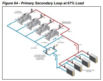
Figure 64 shows the same example operating at 67% capacity. The two-way control valves at the load have reduced the flow in the secondary loop to 643 USgpm. The delta T across the load remains at 10°F. The primary pumps are constant flow pumps sized for their designated chiller’s design flow. It remains constant at 720 USgpm because one of the chillers is off at 67% load. The additional flow not required in the secondary loop (77 USgpm) passes through the common pipe to the chiller return line. The 44°F fluid from the common pipe mixes with the 54°F return fluid to 52.9°F. The chiller maintains its design flow of 720 USgpm with 52.9°F RWT and 44°F LWT. Each chiller sees a load of 89% or an 89-ton load.
The example in Figure 64 demonstrates how diversity is applied to flow in the secondary loop. The variable flow in the secondary loop offers excellent pump operating savings and first cost-saving in pipe sizing. The constant flow in the primary loop provides the chiller with stable operating conditions.

It is important to understand what happens if the design temperature range is not maintained. This is known as low delta T syndrome. Figure 65 shows the previous example with a 268-ton load but only a 7°F delta T. This could be caused by several factors including poor valve selection or dirty coils.
To meet the 268-ton load requirement, the control valve will respond by opening and allowing more flow through the load. The secondary pump will respond in turn by increasing the secondary loop flow to 919 USgpm to meet the load. The primary pump is only supplying 720 USgpm so 199 USgpm will flow “backwards” through the common pipe to meet the 919 USgpm requirements. Two problems now occur. First, the supply fluid temperature in the secondary loop will rise when the primary fluid and the return fluid mix. The higher fluid temperature will cause the control valve to open further, making the problem worse. The second problem is the return water to the chiller is only 51°F so each chiller only sees a 70-ton load. This system will not function well under these conditions.
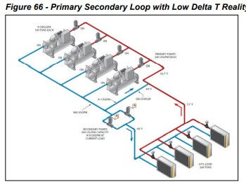
Obviously, the above example can’t occur. Figure 66 shows what does happen. Another chiller has to be started to balance the flow in the primary loop with the flow in the secondary loop.
Although running four chillers provides a working solution, many of the benefits of the primary-secondary system approach are lost. The flow in the secondary loop is high, wasting pumping energy. Four primary pumps have to operate when only three should be operating. Finally, four chillers (and their condenser pumps) are operating at 70% capacity when three can carry the load at 89% capacity.
2.0 Low Delta T Syndrome Causes and Solutions
Many things can lead to low delta T syndrome. The following is a list of common causes and solutions.
2.1 Three-Way Valves
Three-way valves bypass unheated chilled water around the cooling coil and into the return line. They will increase the flow rate of the system while not raising the chilled water temperature.
The solution is not to use them. A common reason for including three-way valves in variable flow systems is to avoid a decoupler. The three-way valves will bypass water when it is necessary to do so, just like a decoupler. They will also bypass water when it is not necessary to do so. Using three-way valves instead of a decoupler wastes pump works and causes the low delta T syndrome.
Another common reason is to maintain some flow in the loop so the water remains at the setpoint. The goal here is to be able to provide cold chilled water to a cooling coil as soon as it calls for it, rather than having to flush the lines. While this may be important in some situations, it generally is not critical in most HVAC applications. Also, consider that chilled water is flowing through the piping at 4 feet per second. Chilled water produced in the basement will travel to the top of a 10-story building in less than 30 seconds.
2.2 AHU Setpoints Lowered Below Design
The control loop for the supply air temperature in a typical AHU is a simple arrangement. There is a temperature sensor in the supply air stream. If the temperature is too high, the controller opens the control valve. If the temperature is too low, the valve closes. A common problem is the temperature setpoint for the supply air is lowered from the original design to the point where the coil cannot produce the requested supply air temperature. In this case, the control loop will keep the chilled water valve wide open in an attempt to cool the water further. The result will be a wide-open valve bleeding chilled water into the return line.
The solution is to reset all the AHU supply air setpoints back to design settings. Often these get changed in the first place because a space served by the AHU is not satisfied. Lowering the setpoint will probably not solve the problem and will create a new problem. Once the settings are back to design, the original problem can be identified and remedied.
2.3 System Components Not Designed for the Same Temperature Range
For a variable flow system to operate properly, all the components must be designed for the same chilled water temperature range including the chillers and the coils at the loads. If the AHUs in a building is designed for a 14°F range while the fan coils are sized for 10°F, it is very likely the system will suffer from low delta T syndrome.
The solution can be very complex. Where possible, converting the system to a common temperature range is desirable but often this is cost-prohibitive. Another solution is to use tertiary piping. Consider a university campus where buildings were built in different eras with different temperature ranges. Now all the buildings are to be served by a common chiller plant. The chiller plant can be operated with one temperature range and a supply water temperature colder than required by any other load. Tertiary piping in each building can be used to match the supply temperature setpoint and temperature range required.
2.4 Coils and Control Valves Not Properly Selected

Improperly selected coils and control valves can lead to excessive chilled water consumption to meet the load requirements.
The solution is to properly select coils and control valves. Control Valve Basics, covers valve selection detail. It is important that the valve actuator have the necessary power to close the valve against the system pressure. Improper coil selection can also lead to difficulties.
2.5 Coils Piped “Backwards”
Coils must be connected so the water flow through the rows of the coil is counterflow to the airflow. When coils are improperly connected, the coil performance can drop by as much as 15%. When this occurs, the chilled water control valve will go wide open because the coil is in effect, 15% undersized. The solution is to properly connect the coils as seen in Figure 67.
2.6 Improper Tertiary Piping
If there is not a difference in the tertiary loop supply temperature and the main supply line, there is a possibility that the two-way control valve that returns tertiary water to the return line will go wide open in an attempt to get the tertiary loop the same temperature as the supply line. This will end up being a short circuit from the supply line to the return.
The solution is to make sure the tertiary loop is operating at a higher temperature than the main supply line.
2.7 Dirty Coils
Dirty coils on either the water or airside will reduce the effectiveness of the cooling coil. The control valve will increase flow in an attempt to offset the coil performance loss and the temperature range will not be maintained.
The solution is to clean the coils.
2.8 Airside Economizers and Make-Up Air Units
Coils that cool supply air with a large percentage of outdoor air are sized for a design day. During periods of lighter loads, the supply air temperature to the coil drops. For instance, when the ambient air temperature is 57°F, an AHU with an economizer will switch to 100% outdoor air and thus the inlet air temperature will now be 57°F. Leaving chilled water can never be warmer than the inlet air temperature. When the inlet air temperature is less than the design return water temperature, low delta T syndrome can occur. In the above example, if the design water temperatures are 44°F supply and 58°F return, it will not be possible to obtain 58°F with 57°F entering the air.
The solution is to reduce the chilled water range to minimize the occurrences where the return water temperature is higher than the supply air temperature. This has to be weighed against the advantages of reducing pumping costs from using a higher chilled water range.
2.9 Chilled Water Reset
Chilled water reset raises the chilled water supply temperature to reduce the lift and thus the compressor work of the chiller. While this is a good goal, it now means a higher supply water temperature than used in the design and selection of the coils. When the reduced load allows a coil to meet the load with warmer water, this approach works. On the other hand, when the warmer water causes the control valves to overflow the coil in an attempt to meet setpoint, then reset can lead to low delta T syndrome.
The solution is a careful evaluation and application of chilled water reset. The first step is whether any energy will be saved at all. Raising the chilled water setpoint will help the chiller. However, it will most likely increase the flow in a variable flow system, which can easily offset any chiller savings. Assuming there are savings available, then a chilled water reset is possible. Chilled water reset should not be based on return water temperature but on valve position at the loads.
3.0 Other Solutions
The following is a list of additional solutions to low delta T syndrome.
3.1 Check Valve in Decoupler
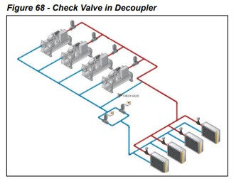
Adding a check valve in the decoupler changes the nature of the primary-secondary system, as seen in Figure 68. When the primary flow exceeds the secondary flow, the system is decoupled and additional primary flow can pass through the decoupler and check valve.
When the secondary flow exceeds the primary flow, however, then the pumps are truly in series. The secondary pump will “pull” water through the primary pump as it attempts to maintain system pressure. The chiller flow rate will increase beyond the design flow rate. It is extremely unlikely that enough flow will be drawn through the chiller to damage it. In most cases, the chiller can handle a 50% increase in flow which would result in a huge pressure drop. It is unlikely the pumps could provide enough head.
By over-pumping a chiller, the system can meet the required flow rate and load, and avoid starting a second chiller and the additional pumps and tower.
Increasing the chiller flow rate offers some unique possibilities. If there is condenser relief available, then the chiller may be able to produce more than its design capacity (For example a 100-ton chiller may produce 110 tons with condenser relief). To take advantage of the extra capacity, the system would have to increase the temperature range across the chiller (difficult to do since the system is typically experiencing just the opposite!) or the flow rate would have to be increased. By over-pumping a chiller, it may be possible to produce more than the design capacity and avoid additional pumps and tower work.
Adding a check valve effectively makes the system variable primary flow during low delta T intervals. System control becomes more complicated as well. How and at what point is a second chiller added? It is recommended that check valves not be added to primary secondary systems as part of the design. If the variable primary flow is the intention, then the system should be designed with that goal in mind. When a system is exhibiting signs of low delta T syndrome, the previous remedies should be investigated first prior to adding a check valve.
3.2 VFD or Dual Compressor Chillers
The main problem with low delta T syndrome is the increase in energy usage due to multiple chillers, pumps and towers operating to meet a light load. VFD and dual compressor chillers offer a different solution. The high part-load efficiency of these kinds of chillers promotes operating two chillers rather than one to meet the load. Two VFD or dual compressor chillers operating partly loaded can consume less energy than one chiller operating fully loaded. If the energy savings offset the penalty of the pumps and tower, then VFD and dual compressor chillers are good solutions to low delta T syndrome.
3.3 Over Size Primary Pumps
Oversizing the primary pumps allows the additional flow to be pumped through the chillers and maintain the primary flow above the secondary flow. Over pumping a chiller can also allow any additional capacity in the chiller to be utilized.
3.4 Reduce Temperature Range on Primary Side
Reducing the chilled water temperature range on the primary side increases the flow rate for the same capacity. During periods of light load, when low delta T syndrome occurs, the lower delta T and higher flow rate on the primary side will counteract problems on the secondary side.
One drawback is the additional pump work on the primary side wastes energy at all operating points. The possible savings offered by avoiding low delta T syndrome at light loads may be offset by the penalty created at other operating points.
3.5 Add Flow Control Valves at Each Coil
Adding flow control valves at each load, rated for the maximum flow rate, will ensure the load won’t consume too much-chilled water. From the chiller plant’s perspective, this will avoid low delta T, however, space serviced by the coil may not be satisfied. In addition, most control valves create a pressure drop that the chilled water pumps must be sized to overcome. Overcoming the additional pressure drop will add to the annual cost of operating the pumps.
3.6 Variable Primary Flow
Low delta T syndrome occurs because of issues at the loads (coils). These will happen with the variable primary flow or primary-secondary systems. Variable primary flow (VPF) does allow several solutions to be easily implemented:
Do not have a decoupler that allows returning chilled water to flow into the supply side. Return chilled water will raise the supply water temperature and exacerbate the problem.
VPF allows chillers to be over-pumped. See Check Valve in Decoupler.
VPF systems typically have flow meters, which can help the operator recognize a low delta T situation and be used by the BAS to remedy the problem.


Welcome to Kelvin Mech – a leading name in heating, ventilation, and air conditioning solutions across the country. With a strong presence as an established HVAC contractor in Mumbai, Delhi, and Pune, we specialize in offering customized HVAC design, installation, and maintenance services for commercial, industrial, and residential projects.