Parallel Chiller System
- Scholenberg
- Dec 11, 2021
- 4 min read

To provide some redundancy in the HVAC design, most designers will require two or more chillers. Multiple chillers also offer the opportunity to improve on overall system part load performance and reduce energy consumption. Parallel chiller plants are straightforward to design and are easily modified for variable primary flow.
1.0 Basic Operation

Variable flow systems are covered in Primary Secondary Systems and Variable Primary Flow Design.
For constant flow systems, the chilled water temperature range varies directly with the load. Depending on load diversity, the chiller design temperature range will be less than the temperature range seen at each load. In this case, the chiller temperature range is 8°F while the cooling coil range is 10°F (Refer to Piping Diversity). The overall result is increased chilled water pump and pipe capital cost plus higher annual pumping cost.
2.0 Basic Components
2.1 Chillers
In most cases, the sum of the chiller capacities meets the design for the building or process. Additional capacity can be added, if required, by over sizing the chillers. It is common for parallel chillers to be the same size and type although this not a requirement. Water cooled, air cooled, or evaporatively cooled chillers can be used. Air and evaporatively cooled chillers do not require a condenser loop including piping, cooling tower, and pump.
2.2 Pumps
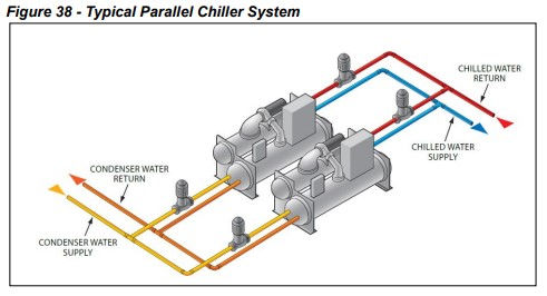
Pumps can be constant or variable flow. Pump basics are covered in Pumping Basics. The chilled water pump is sized for the design flow rate. Figure 38 shows dedicated chilled water pumps, each providing flow to their own chiller. An alternative method is to have one large pump that serves both chillers. The pumps and piping are sized for the design condenser flow for each chiller. Whenever the chiller operates, the condenser pump operates. With the configuration shown in Figure 38, it can be seen that if you were at 50% load, you would only need to run one condenser and one evaporator pump, not all four.
2.3 Cooling Towers
Water cooled chillers will require cooling towers. A common cooling tower is also possible but not recommended for parallel chillers. Cooling towers are covered in Cooling Tower Basics.
3.0 Parallel Chiller Sequence of Operation
Parallel chiller plants create a unique situation when used in a constant flow system. Consider a two chiller system operating at less than 50% of total plant load. From a chiller performance aspect, turning off one chiller and operating the other at a higher capacity may be desirable if the running chiller will operate at its peak efficiency. However, this will not happen if the idle chiller is not isolated from the water loop. For example at 50% capacity, the return water will be 49°F in a typical AHRI plant of ten degree chilled water range. The chiller that is turned off will let the water pass through it unchanged. The operating chiller will only see a 50% load (49°F return water), and will cool the water down to the set point of 44°F. The two chilled water streams will then mix to 46.5°F supply temperature.
If the system is operated in this manner, the warmer chilled water will cause the control valves to open (increase flow) to meet the space requirements. An iterative process will occur and the system may stabilize. The issue is whether the cooling coils can meet the local loads with the higher chilled water temperature. Depending on the actual design conditions, the building sensible load could be met but high chilled water temperature will make it difficult to meet the latent load. Since this scenario is likely to occur during intermediate weather, dehumidification may not be an issue. In areas where humidity is an issue, this arrangement can result in high humidity within the space.
One solution is to operate both chillers all the time. This works and is a simple solution; however, it may not be energy efficient and causes avoidable equipment wear.
Another possibility is to lower the operating chiller’s set point to offset the mixed water temperature. This also works but has some difficulties. Lowering the chilled water setpoint requires the chiller to work harder, lowering its efficiency. In extreme conditions, it can cause chiller stability issues.
ASHRAE Standard 90.1 requires that when a parallel chiller is shut down, the total plant flow rate must be reduced accordingly. This is most often done in constant flow systems by stopping chilled water pumps and isolating any chillers that are not operating with automatic control valves. With reduced flow, all the cooling coil control valves will adjust to maintain their design setpoint. Standard 90.1 also requires that the chilled water supply temperature be reset upward whenever possible for constant volume chilled water systems over 25 tons.
The safe answer is to operate both chillers all the time chilled water is required, however, this is as expensive as operating a single chiller plant. Staging on the pumps and cooling towers is similar to that outlined for single chillers. Refer to Single Chiller Sequence of Operation.
Air cooled chillers have their own uniqueness in parallel operation. Refer to Air Cooled Chiller System Design for information on operating parallel air cooled chillers. Magnetic bearing chillers also offer an added savings to this plant configuration. If two magnetic bearing chillers are used, the controllers will maximize savings by operating both chillers at part load. This gains the advantage of best total operation efficiency for the chillers. Again, pumps should also have VFDs so that they can turn down to match the load as well.


Comments